Exploring Surface-Mount vs. Through-Hole Technology for Your PCBA Needs
Reading this on your smartphone or PC, you are utilizing one or more of what is known as a printed circuit board assembly (PCBA) — the heart inside all electronic devices. Instead of pumping blood, PCBAs pump out power and data along conductive pathways and components (wires, connectors, etc.) which keep the electronic communication flowing along the circuits.
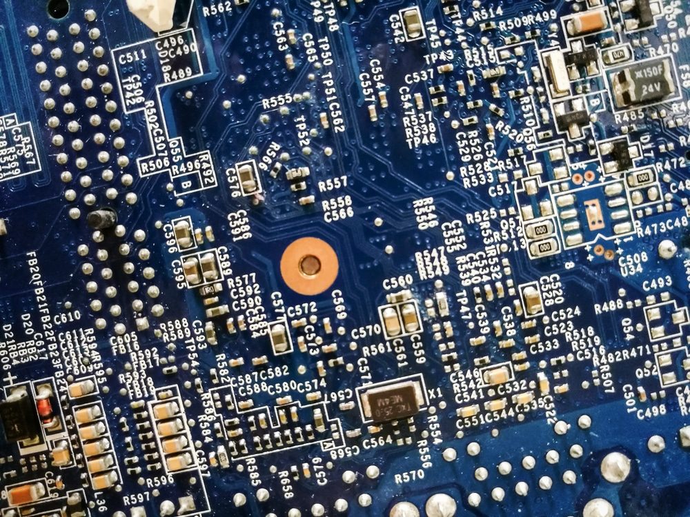
PCBAs resemble tiny, (often) green, rectangular cities with miniature buildings and roadways running to and from each other. They’re the finished product after printed circuit boards (PCBs) are made viable by strategically affixing (or soldering) all necessary electronic components to their outer layers. During this phase, there are two mounting methods to choose from — surface-mount technology (SMT) and through-hole technology (THT) — and both technologies can be used on the same board, if necessary.
THT was the sole mounting process available up until the mid-80s when SMT became the prevalent method, used in over 90% of PCBAs today. However, THT and its unique benefits remain the preferred option for special applications.
At CAI, we integrate PCBAs in specialty vehicles, light panels, and more, and we’re proficient in both SMT and THT methods. For expert help assembling your PCBAs, talk to us today.
Surface-Mount Technology
The surface-mounting process uses a pre-programmed robotic device called a pick-and-place machine (P&P) to speedily and precisely place components — such as capacitors, resistors and integrated circuits — directly onto the surface of a PCB. Once placed, the components, known as surface-mount devices (SMDs), are soldered to the board, thus completing the mounting process.
Pros
With its sophisticated automation and no need for hole drilling, SMT can place components nearly 10 times faster than THT and allow for quick soldering, saving time and money while not sacrificing quality. With smaller or no leads and the ability for SMDs to be placed on both sides of the PCB in higher densities, SMT allows for significantly smaller boards than THT, a big advantage for today’s compact electronic devices.
Cons
For components designed to endure a high degree of mechanical and environmental stress including intense heat, surface-mounting can be less reliable than through-hole mounting. Meanwhile, SMT isn’t ideal for manual or low-automation fabrication and the one-off prototyping and small-scale production associated with it.
Your PCBA Needs with Through-Hole Technology
Some components, like large transformers, capacitors and certain power semiconductors, aren’t suitable for surface mounting, making through-hole technology (first used in 1950s’ computers) a still relevant and valuable option.
THT involves inserting pin-through hole components through (often copper-plated) holes pre-drilled completely through the printed circuit board. The ends (or leads) are threaded through, forming a crisscross pattern on the other side where they are attached to pads with wave (or reflow) soldering gear.
Pros
Because their leads run through the board, THT creates much stronger mechanical bonds between components and the circuit board, compared to SMDs which are secured only by soldering onto the board surface. Widely used in aerospace and military electronics, THT remains the better choice for components that have to withstand extreme mechanical and environmental stress, high voltage, and/or extreme temperatures. Easy to swap out, THT components also make prototyping and testing simple and easy.
Cons
THT is often a more tedious and expensive process than SMT. Unlike SMT’s use of both sides, THT components are restricted to one side of the PCB, and having to drill holes through all of the PCB layers further limits total usable space. Meanwhile, THT’s soldering points can be less reliable than those used with SMT.
The best mounting process for your PCBA components depends on many factors including their intended use and future environment. Keep in mind that you can use a mix of techniques on the same boards.
As experts in PCBA manufacturing, we’re here to help you make all the right choices when it comes to your electronic component needs.
