Ensuring Optimal Performance, Endurance and Safety,Cable Assemblies Must Undergo a Thorough Examination
Cable assemblies are the essential power and data carriers behind the machines, devices and appliances we enjoy and rely on each and every day. Before cable assemblies are shipped out and installed, they must undergo thorough testing to ensure they will effectively and consistently do their jobs for their specific applications once installed.
Depending on a cable assembly’s intended use and future environmental conditions, there are many mechanical, environmental and electrical testing procedures used to measure performance, endurance and safety. For instance, assemblies made for medical or aerospace devices undergo a different overall set of tests than those made for a car stereo.
Tests can be performed on each cable produced or on an acceptance quality limit (AQL) sample size. Many tests require specialty fixtures and testing equipment and the know-how to use them in order to diagnose and troubleshoot. While most tests are applied in the final stage of the manufacturing process, some need to be performed in-process to demonstrate that a step was completed.
For over 35 years, CAI has been a trusted maker of cable assemblies and wire harnesses, meeting all volume needs of clientele in diverse industries across the globe. Contact them today for expert help bringing your electrical systems to life.
Here are some of the most common tests that me be specified for cable assembly quality assurance:
Visual Test
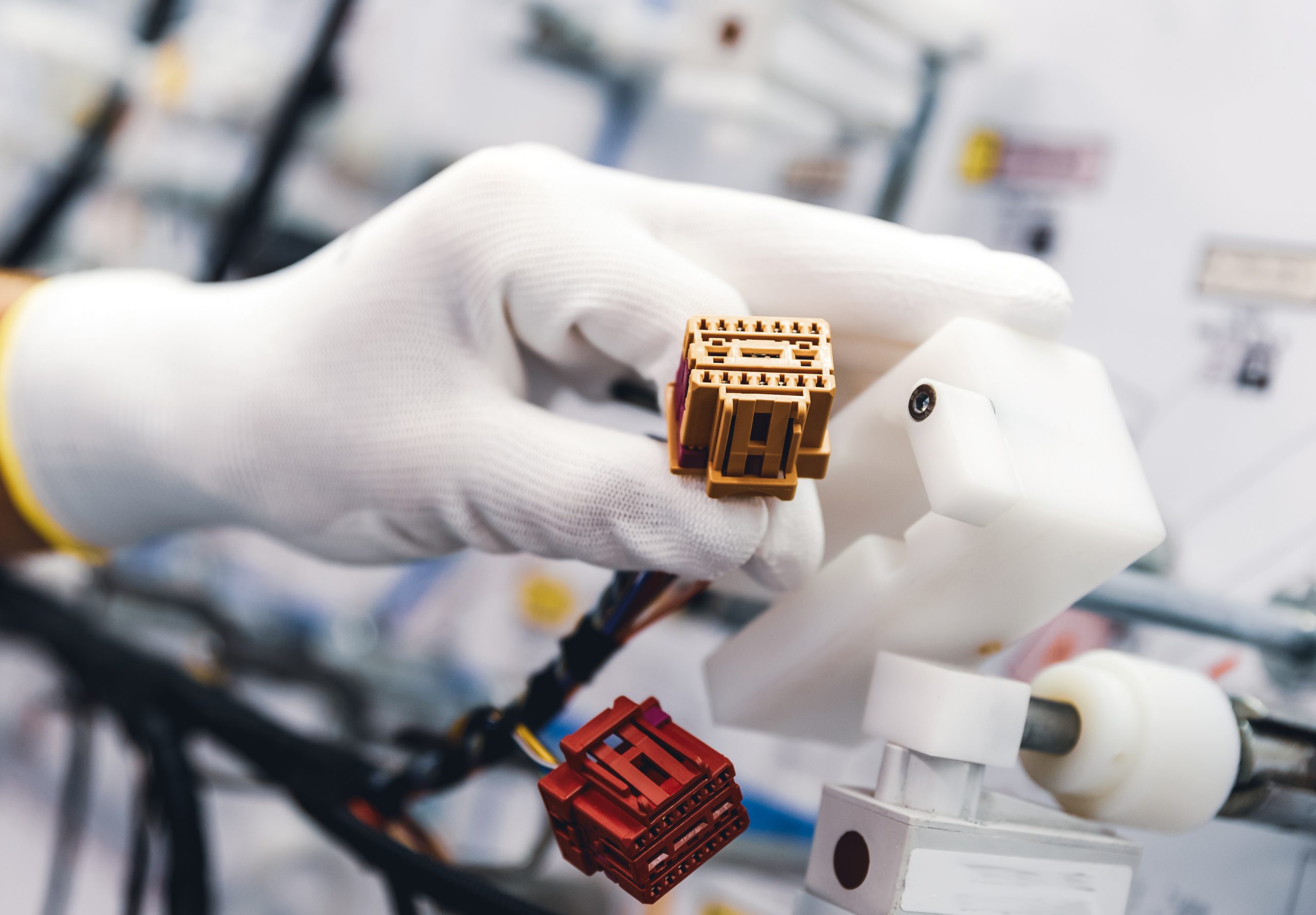
A simple yet significant test is the visual inspection of the entire assembly to assess workmanship and detect obvious faults. Here is where the manufacturer looks it over to check for the proper materials, markings, finish, design and construction. They search for signs of damage that may have happened during the manufacturing process, inspect connectors and sockets, and make sure enclosures are secured safely.
Continuity Test
Of all the tests, this would be the most pervasive, used to confirm that connectors and wires are correctly assembled by verifying proper current flow through the cable. A multimeterdevice is used to send a small voltage between two or more test points which measures the circuit’s resistance (or continuity).
The test reveals open circuits caused by a damaged conductor or broken wire. A high resistance reading means a flawed connection that’s at risk of failing. Multimeters often verify electrical continuity with an audible beep, and should there be an open circuit, it displays the corresponding open loop message.
Hipot Test
Also called a dielectric strength test, the hipot (short for high potential) test evaluates the cable’s insulation jacket for defects, gaps, or contamination that may have happened at some point in the production process. In addition, it also checks for electrical current leakage and short circuits.
A high voltage is passed across two conductors to create stress on the insulation and connections. The circuit must withstand the high voltage for a specified amount of time to ensure that the cable assembly will be safe to consistently use with the lower voltage output it was designed for.
Milliohm Test
Used to measure extremely low-resistance connections in cable assemblies, the milliohm test helps determine the quality of the electrical connection and that it operates within a predetermined range of acceptable values. A milliohm meter assesses the low-resistance values mostly between the cable and ground through a 4-terminal measurement method where a current is applied to a portion of the assembly.
Two of the terminals are used to measure voltage while the other two are used for current sensing. A common requirement is that the assembly measures 2.5 milliohms between two ground points. If resistance is higher, the cable must be reevaluated or rejected.
Pull Test
The cable assembly is pulled at a specific load and rate based on the wires and connectors involved. Connected to the wires, a motorized pull tester measures the amount of pulling force applied. The strength of the wire, connectors, and crimp joints can then be measured in several ways.
Pull and break method applies force until the wire or terminal breaks. For pull, hold and break, a pull is held at a certain rate before additional force is increased in increments until the wire or connectors fail. Pull and hold involves a pulling force held at a specific rate for a certain length of time. The pull and release method pulls the assembly a specific length but doesn’t hold the pull.
Flex/Bend Tests
Throughout its life, a cable assembly may be expected to withstand a good deal of bending and twisting, with as little signal interruption or damage to the jacket or insulation as possible.
To assess a cable assembly’s resistance to bending damage, a cable’s one end is typically attached to a bend/flex machine while the other end may be tied into a knot or have a weight attached to the other end as the machine bends the cable to a 90-degree angle. A rolling bend test requires the other end to be attached to a swing-arm mechanism that continuously flexes the cable by swinging it back and forth at a 180-degree arc.
Environmental Tests
Many cable assemblies have to withstand constant threats in their future environments, often requiring compliance to product safety specification standards by demonstrating resilience to harsh conditions such as extreme temperatures, high humidity, chemical exposure, submersion, condensation, fungus or saltwater which can age, corrode or degrade them without proper protection. This can necessitate the use of highly specialized equipment that simulates these conditions.
Signal Integrity Tests
Including error testing, crosstalk testing, and testing whether signal strength can be maintained with the addition of splices, filters or connectors, signal integrity tests typically requires connecting the cable assembly to a time-domain reflectometer (TDR) or a vector-network analyzer (VNA) through a test fixture.
At CAI, rest assured that your finished custom cable assemblies will meet all your electrical, mechanical and environmental requirements. Reach out to discuss your project today.


